Not known Factual Statements About Wedge Barriers
Wiki Article
A Biased View of Wedge Barriers
Table of ContentsThe smart Trick of Wedge Barriers That Nobody is Talking AboutWedge Barriers Things To Know Before You Buy

The spring rod 58 is paired to a webcam(e. g., cam 80 revealed in FIG. 4) of the training mechanism 50. The springtimes 60 disposed about the springtime rod 58 are held in compression by springtime sustains 62, consisting of a fixed springtime assistance 64. That is, the set springtime assistance 64 is taken care of about the foundation 14 et cetera of the bather 10.
About Wedge Barriers
g., spring support 65 )might be taken care of to completion of the springtime pole 58 to make it possible for compression of the springs 60. As the springs 60 are pressed in between the springtime supports 62, the springtime assembly 54 generates a force acting on the web cam combined to the spring pole 58 in a direction 66. The continuing to be force used to the cam camera deploy the wedge plate 16 may might provided by an electromechanical actuator 84 or other actuator. As such, the springtime setting up 54 and the actuator 84(e. g., electromechanical actuator)may operate with each other to equate the web cam and lift the wedge plate 16.
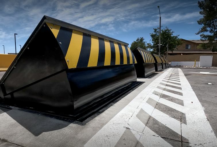
As pointed out over, the spring assembly 54 puts in a continuous pressure on the webcam, while the electromechanical actuator might be managed to exert a variable pressure on the camera, therefore enabling the lifting and lowering( i. e., deploying and retracting )of the wedge plate 16. In specific embodiments, the constant force used by the spring setting up 54 may be adjustable. g., electromechanical actuator) is disabled. As will certainly be valued, the spring setting up 54 might be covered and shielded from debris or various other aspects by a cover plate(e. g., cover plate 68 shown in FIG. 4) that may be substantially flush with the raised surface 38 of the structure 14. As mentioned above, in the deployed setting, the wedge plate 16 offers to obstruct gain access to or traveling beyond the barrier 10. The obstacle 10(e. g., the wedge plate 16 )may block pedestrians or vehicles from accessing a residential property or path. As gone over over, the obstacle 10 is connected to the find more information support 30 secured within the structure 14,
front braces 71. Consequently, the linkage settings up 72 might pivot and rotate to make it possible for the collapse and extension of the linkage assemblies 72 throughout retraction and release of the bather 10. The affiliation settings up 72 reason activity of the wedge plate 16 to be restricted. As an example, if an automobile is traveling in the direction of the released wedge plate 16(e. For instance, in one condition, the safety legs 86 may be prolonged duringupkeep of the obstacle 10. When the security legs 86 are deployed, the safety and security legs 86 sustain the weight of the wedge plate 16 versus the surface 12. As an outcome, the lifting mechanism 50 might be shut off, serviced, removed, replaced, etc. FIG. 5 is partial viewpoint sight of a personification of the surface-mounted wedge-style obstacle 10, highlighting the webcam 80 and the cam surface areas 82 of the lifting mechanism 50. Specifically, two webcam surfaces 82, which are described as reduced webcam surfaces 83, are placed below the cam 80. The reduced cam surface areas 83 might be taken care of to the surface area 12 (e. For instance, the reduced webcam surfaces 83 and the installing visit site plate 85 may create a single item that is protected to the anchor 30 by bolts or various other mechanical bolts. In addition, two camera surfaces 82, which are described as top cam surfaces 87, are placed over the cam 80 and combined to (e. In other personifications, stepping in layers or plates might be positioned between the surface 12 and the reduced web cam surface areas 83 and/or the wedge plate 16 and the top web cam surfaces 87 As discussed above, the webcam 80 translates along the webcam surfaces 82 when the wedge plate 16 is raised from the withdrawed position to the released setting. In addition, as stated over, the spring assembly 54 (see FIG. 3 )may offer a force acting on the webcam 80 in the direction 102 by means of springtime rod 58, which might decrease the pressure the electromechanical actuator 84 is required to use to the camera 80 in order to actuate and lift the wedge plate 16. 1 )to the deployed placement(see FIG. 4). As shown, the web cam 80 includes track wheels 104(e. g., rollers), which call and convert along the camera surfaces 82 throughout operation.
Report this wiki page